Overview
- Faults are fractures in the Earth's crust along which blocks of rock have moved relative to one another, and they are classified by the direction of that relative motion into three end-member types: normal faults, where the hanging wall drops down under extension; reverse and thrust faults, where the hanging wall rides up under compression; and strike-slip faults, where the two blocks slide horizontally past each other.
- Anderson's 1951 theory of faulting links each fault type to a distinct stress regime defined by the orientations of the maximum, intermediate, and minimum principal stresses, and it predicts that fresh faults will form at characteristic angles to those stress axes consistent with the laboratory friction laws established by Byerlee in the 1970s.
- Real fault systems are recorded in the geomorphology of the Wasatch Front, the San Andreas Fault, the Keystone Thrust, and the Main Himalayan Thrust, and the great earthquakes that nucleate on them, including the 1906 San Francisco rupture and the 2004 Sumatra-Andaman megathrust, are interpreted today through focal mechanisms and moment tensors that recover the same Andersonian categories from seismic radiation patterns.
A fault is a fracture or zone of fractures in the Earth's crust across which one block of rock has moved measurably relative to the other. Faults are the brittle response of the upper crust to stresses imposed by plate motion, gravitational loading, and the cooling of the lithosphere, and they are the fundamental structures along which most earthquakes nucleate. The geological classification of faults rests on a simple kinematic question: in what direction did one side of the fracture move with respect to the other? The answer divides faults into three end-member types — normal, reverse (or thrust), and strike-slip — together with hybrid oblique-slip faults that combine vertical and horizontal motion. This taxonomy was placed on a quantitative mechanical footing by the Scottish geologist E. M. Anderson, whose 1951 monograph The Dynamics of Faulting showed that the three fault classes correspond to three distinct configurations of the principal stress axes within the crust.1, 5
The classification matters because the type of fault dictates almost everything about its expected behaviour: the orientation of the rupture plane in the subsurface, the geomorphic landforms it produces at the surface, the kind of plate boundary it belongs to, the magnitude of the earthquakes it can host, and the way it transfers and dissipates strain over geological time. The same Andersonian framework is used today to interpret moment tensors recovered from broadband seismograms, to design probabilistic seismic hazard maps for cities such as Salt Lake City and San Francisco, and to read the structural history of ancient mountain belts from the rocks they have left behind.4, 20, 21
The anatomy of a fault
Before any classification can be applied, the geometric vocabulary of a fault has to be established. A fault plane is described by its strike, the compass direction of its intersection with a horizontal surface, and its dip, the angle that the plane makes below the horizontal measured perpendicular to the strike. A vertical fault has a dip of 90 degrees, a horizontal one a dip of zero. Where the fault is inclined, the rock mass resting on top of the dipping plane is the hanging wall, and the mass beneath it is the footwall. The terms originate in nineteenth-century mining, when miners working a metal vein along an inclined fracture would hang their lanterns from the rock above their heads and stand on the rock beneath their feet.5, 6
The slip vector describes the actual direction and magnitude of relative motion of the two walls along the plane. Its orientation within the fault surface is given by the rake (or pitch) angle, measured from the strike line. A rake of 90 degrees, with the hanging wall moving directly down the dip, defines pure normal slip; a rake of 270 degrees (or −90 degrees), with the hanging wall moving directly up the dip, defines pure reverse slip; rakes of 0 and 180 degrees correspond to pure strike-slip motion in opposite senses. Any rake between these end members defines an oblique-slip fault, and modern earthquake catalogues record the entire spectrum.6, 18
Faults are not infinitesimally thin surfaces. Even a single planar fracture is bordered by a zone of damaged rock, and large faults contain a structured fault zone consisting of a high-strain core surrounded by progressively less deformed damage zones. The rocks within these zones — cataclasites, fault gouge, fault breccia, mylonites, and pseudotachylytes — record the temperature, pressure, and rate at which slip occurred. The classic 1977 classification by R. H. Sibson divides fault rocks into a brittle suite produced in the upper, seismogenic crust and a ductile suite produced in the deeper, plastic regime, providing a way of reading the depth at which an exhumed fault originally moved.7
Anderson's stress theory of faulting
Anderson's central insight was that the Earth's surface is itself a free surface that cannot support a shear stress, so one of the three principal stress axes — the directions along which the stress tensor reduces to a pure compression or tension — must be vertical near the surface. The other two are horizontal. Three permutations are possible, and they correspond exactly to the three fault types observed in nature. When the maximum compressive stress σ1 is vertical, the crust is being squeezed downward and stretched horizontally, and the resulting faults dip steeply and accommodate extension as normal slip. When σ1 is horizontal and the minimum stress σ3 is vertical, the crust is being compressed horizontally and the resulting faults dip gently and accommodate shortening as reverse slip. When the intermediate stress σ2 is vertical and both σ1 and σ3 are horizontal, the resulting faults are nearly vertical and accommodate horizontal slip in opposite directions on either side — strike-slip motion.1, 5, 20
Anderson's three fault classes and their stress regimes1, 5, 20
| Fault type | Vertical stress axis | Crustal regime | Typical dip of fresh fault | Sense of slip | Plate-tectonic setting |
|---|---|---|---|---|---|
| Normal | σ1 (maximum) | Extension | ~60° | Hanging wall down | Divergent boundaries, rifts, back-arcs |
| Reverse / thrust | σ3 (minimum) | Compression | ~30° | Hanging wall up | Convergent boundaries, fold-and-thrust belts |
| Strike-slip | σ2 (intermediate) | Shear | ~90° | Horizontal, lateral | Transform boundaries, transcurrent zones |
| Oblique | None purely vertical | Mixed | Variable | Combined dip- and strike-slip | Transpressional or transtensional margins |
The dip angles in the table are not arbitrary. They follow from the assumption that fresh faults form in intact, isotropic rock at the orientation of maximum shear stress modified by the internal friction of the material. For a typical coefficient of internal friction near 0.6, the predicted angle between σ1 and the fault plane is about 30 degrees. Since σ1 is vertical for normal faulting, the resulting plane dips at about 60 degrees; since σ1 is horizontal for reverse faulting, the plane dips at about 30 degrees; for strike-slip faulting both compatible planes are vertical and intersect at 60 degrees in plan view. These predicted orientations match an enormous body of field measurements remarkably well, and where observed faults depart from them — for example, the very low-angle detachment faults of metamorphic core complexes — an explanation in terms of pre-existing weaknesses, fluid pressures, or finite rotation has to be supplied.1, 2, 11
Anderson's framework also makes a quantitative prediction about how the three regimes are bounded. R. W. Simpson recast the theory in 1997 as a continuous parameter Aφ that ranges from 0 (pure normal) through 1 (pure strike-slip) to 2 (pure reverse), allowing intermediate stress states such as transtension and transpression to be described in a single number and mapped across regions. The parameter is now used to compile global stress maps from earthquake focal mechanisms and borehole breakouts.20, 21
Friction, fluid pressure, and Byerlee's law
Anderson's theory predicts the orientation of new faults but not the absolute strength of the crust. That problem was attacked experimentally in the 1960s and 1970s by James Byerlee, who measured the shear stress required to slide pre-cut samples of common crustal rocks — granite, sandstone, dolomite, marble, and many others — against themselves under increasing normal stress. He found that the relationship was nearly independent of rock type and described by two linear segments, now called Byerlee's law: at normal stresses below about 200 megapascals, the shear stress at slip is approximately 0.85 times the normal stress, and at higher normal stresses the relationship becomes τ = 50 MPa + 0.6σn. The implied coefficient of friction lies between 0.6 and 0.85 for almost all crustal rocks, a range so narrow that the value is treated as a property of the upper crust as a whole.2, 4
Combined with Anderson's stress orientations, Byerlee's law sets the strength envelope of the seismogenic crust. It predicts that normal faults can support smaller differential stresses than strike-slip faults, which in turn support smaller stresses than thrust faults — a prediction borne out by the maximum earthquake magnitudes observed on each fault class. It also explains why the deep crust deforms aseismically: at depths greater than about 15 kilometres in continental crust, temperatures rise above the value at which quartz begins to flow plastically, and the frictional strength predicted by Byerlee's law is exceeded by the much lower strength of dislocation creep. The transition from frictional to plastic behaviour defines the base of the seismogenic zone, the depth interval within which earthquakes nucleate.4, 7
There is a major qualifier. M. K. Hubbert and W. W. Rubey demonstrated in 1959 that high pressures of fluid trapped in the pores and fractures of a rock reduce the effective normal stress on a fault surface, and so reduce the shear stress required for slip. For a fluid pressure approaching the lithostatic load, the effective normal stress falls toward zero, and the resistance to faulting can be made arbitrarily small. This insight resolved the long-standing “paradox of overthrusting,” the puzzle of how thrust sheets hundreds of kilometres long, such as the Glarus nappe of the Swiss Alps, could be pushed across nearly horizontal surfaces without disintegrating: the rock at the base of the sheet was pressurised by trapped water, and friction was correspondingly low. Modern measurements of pore pressure in active subduction megathrusts, including the Nankai and Hikurangi margins, confirm that fluid pressures close to lithostatic are widespread and that they exert first-order control on whether a fault slips seismically or aseismically.3, 4
Normal faults and extensional tectonics
Normal faults form where the crust is being stretched. The hanging wall slides down the fault plane relative to the footwall, accommodating horizontal extension by allowing the crust to thin vertically. Where two normal faults dip toward each other, the down-dropped block between them is called a graben; the up-thrown block on either side is a horst. Where extension is accommodated by a single dominant fault rather than a symmetric pair, the resulting asymmetric basin is a half-graben, and this geometry dominates the topography of the western United States.6, 19
_2_(25177401995).jpg)
The Basin and Range Province of Nevada, Utah, and adjacent states is the type example of continental extension. Beginning roughly 17 million years ago in the early Miocene, this region began to pull apart in an east-west direction, producing the alternating mountain ranges and intervening basins that characterise the modern landscape. Each range is a tilted fault block bounded on one side by an active or recently active normal fault; each basin is the corresponding half-graben filled with eroded sediment. Estimates of total extension across the province at 39°N are on the order of 250 to 300 kilometres since the Miocene, roughly doubling the original width of that part of the crust.19
The eastern margin of the Basin and Range is marked by the Wasatch Fault, a 343-kilometre normal fault zone that runs along the western front of the Wasatch Range in Utah. The Wasatch is the longest continuous active normal fault in the contiguous United States and the topographic boundary between the extending Basin and Range and the more stable Colorado Plateau and Middle Rocky Mountains to the east. Trenching investigations led by the U.S. Geological Survey have identified at least 22 surface-rupturing earthquakes on the central segments of the Wasatch fault zone in the past 6,000 years, with average recurrence intervals of about 1,200 years and Holocene slip rates of 1 to 2 millimetres per year on the most active segments. The fault is divided into ten geometrically distinct segments, five of which have been seismically active during the Holocene, and each is capable of generating an earthquake of magnitude 7 or greater. About 80 percent of Utah's population lives within the immediate hazard zone of these segments.10
Anderson's theory predicts normal-fault dips near 60 degrees, and the steeper segments of the Wasatch and similar faults match this prediction. But many of the largest extensional structures in the Basin and Range have nothing of the kind. In 1981, Brian Wernicke described a class of low-angle normal faults — detachment faults dipping at 30 degrees or less — along which mid-crustal rocks have been exhumed beneath dramatically thinned upper-crustal blocks. The detachments root into ductile shear zones in the lower crust, and where the lower-crustal rocks are unroofed at the surface they form domal exposures called metamorphic core complexes. Lister and Davis documented the type examples in the lower Colorado River region of Arizona, Nevada, and California, where Tertiary detachments have brought amphibolite-grade metamorphic rocks to the surface beside unmetamorphosed upper-plate sedimentary cover.11, 12
Low-angle normal faults are mechanically problematic precisely because they violate Anderson's prediction. Slip on a 20-degree normal fault under standard Byerlee friction would require either a horizontal σ1 stronger than the vertical lithostatic load — which is impossible by definition of normal faulting — or near-lithostatic fluid pressures, or a fault with a friction coefficient far below the Byerlee value. Each option remains an active research question, and the very rarity of recorded earthquakes on low-angle normal faults is itself evidence that they may slip largely aseismically once they have rotated past the steep orientation in which they originally formed.4, 11
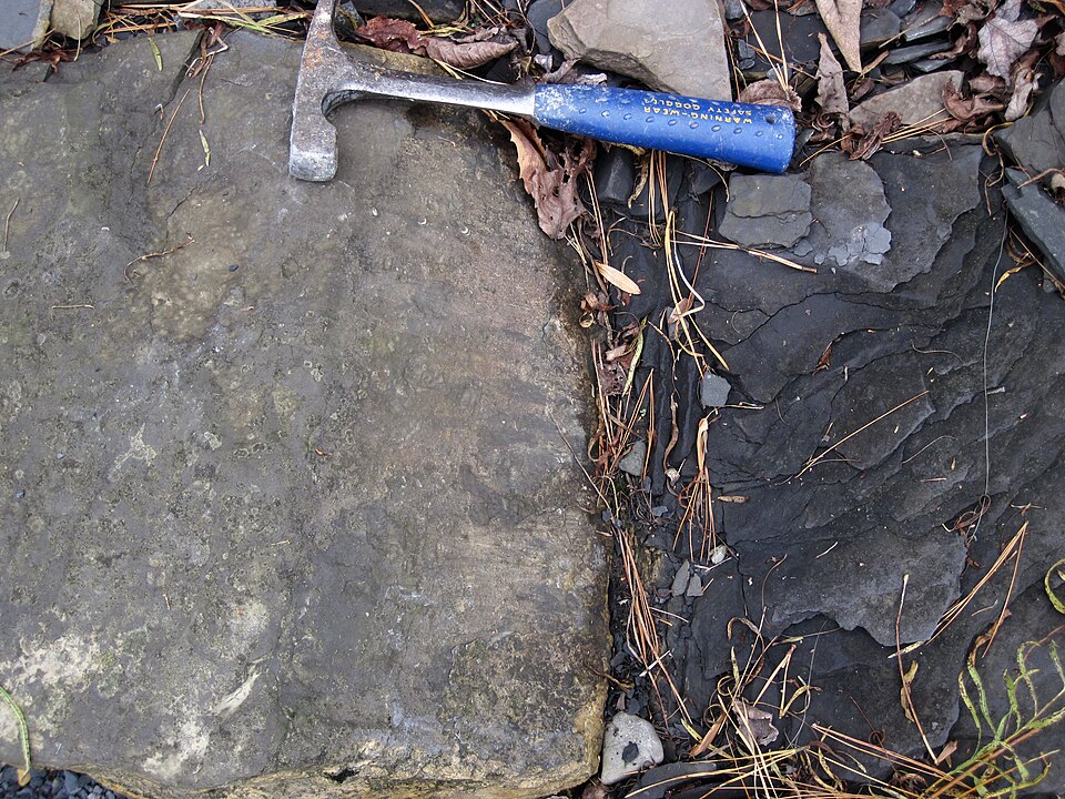
Reverse and thrust faults
Reverse faults form where the crust is being shortened horizontally. The hanging wall moves up the fault plane relative to the footwall, stacking older rocks over younger ones and thickening the crust. By convention, a reverse fault dipping more steeply than 45 degrees retains the simple name reverse fault, while one dipping less steeply — that is, the geometry predicted by Anderson for fresh compressional fractures — is called a thrust fault. The largest thrusts are the megathrusts of subduction zones, where the entire interface between two plates is a single shallowly dipping fault hundreds of kilometres long.5, 6
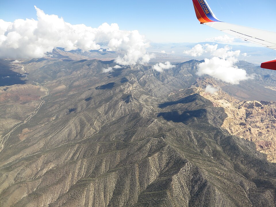
.jpg)
The classic continental example is the Keystone Thrust in the Spring Mountains west of Las Vegas, Nevada, part of the Sevier fold-and-thrust belt that swept eastward across western North America during the Cretaceous and early Cenozoic. Strain was transferred to the Keystone Thrust by about 99 million years ago, and the thrust sheet itself has carried a Palaeozoic-to-early-Mesozoic carbonate succession more than four kilometres thick over a channelled erosion surface cut into the Jurassic Aztec Sandstone. The cumulative horizontal displacement on the Keystone is at least 25 kilometres and probably twice that, illustrating exactly the “overthrust paradox” that Hubbert and Rubey set out to solve. At Red Rock Canyon, the contact is exposed as the dark grey Cambrian Bonanza King Dolomite resting directly on the brilliant red and white Jurassic sandstone, an unmistakable visual record of older rocks emplaced atop much younger ones.3, 5
Active continental thrusting is best studied today on the Main Himalayan Thrust, the gently north-dipping décollement that underlies the entire Himalayan range and accommodates the convergence of India and Eurasia. The Main Himalayan Thrust dips at about 10 degrees and is the largest active continental megathrust in the world. Geodetic measurements across the Nepal Himalaya show convergence rates of 17 to 21 millimetres per year, with about half of that absorbed on the Main Himalayan Thrust and the remainder distributed across splay structures including the Main Frontal Thrust, the Main Boundary Thrust, and the Main Central Thrust farther into the mountain belt. The thrust is locked from the surface to a depth of roughly 100 kilometres downdip, accumulating an elastic moment deficit of order 7 × 10¹⁹ newton-metres per year that is released in great earthquakes such as the magnitude 7.8 Gorkha event of 2015.15
Subduction megathrusts release the largest earthquakes on Earth. Every recorded shock of magnitude 9.0 or greater has nucleated on a subduction interface. The 2004 Sumatra-Andaman earthquake, which ruptured the contact between the Indo-Australian and Sunda plates, propagated northward from its hypocentre off northern Sumatra for approximately 1,300 kilometres and lasted at least ten minutes — the longest fault rupture and the longest source duration ever recorded instrumentally. The rupture front advanced at an average velocity of 2 to 3 kilometres per second across a fault patch roughly 1,300 kilometres long and 150 to 200 kilometres wide, with peak slip near 15 metres on average and considerably more locally. The displaced seafloor generated a tsunami that killed approximately 230,000 people across fourteen countries.14
Strike-slip faults
Strike-slip faults accommodate horizontal motion of one block past another along a nearly vertical plane. The sense of motion is described from the perspective of an observer standing on one side of the fault and looking across it: if the opposite block has moved to the right, the fault is right-lateral or dextral; if to the left, it is left-lateral or sinistral. Pure strike-slip faults produce no vertical displacement, and where they reach the surface in regions of low relief they are often expressed only as linear topographic features — offset stream channels, sag ponds in releasing bends, and pressure ridges in restraining bends — rather than as scarps.5, 6
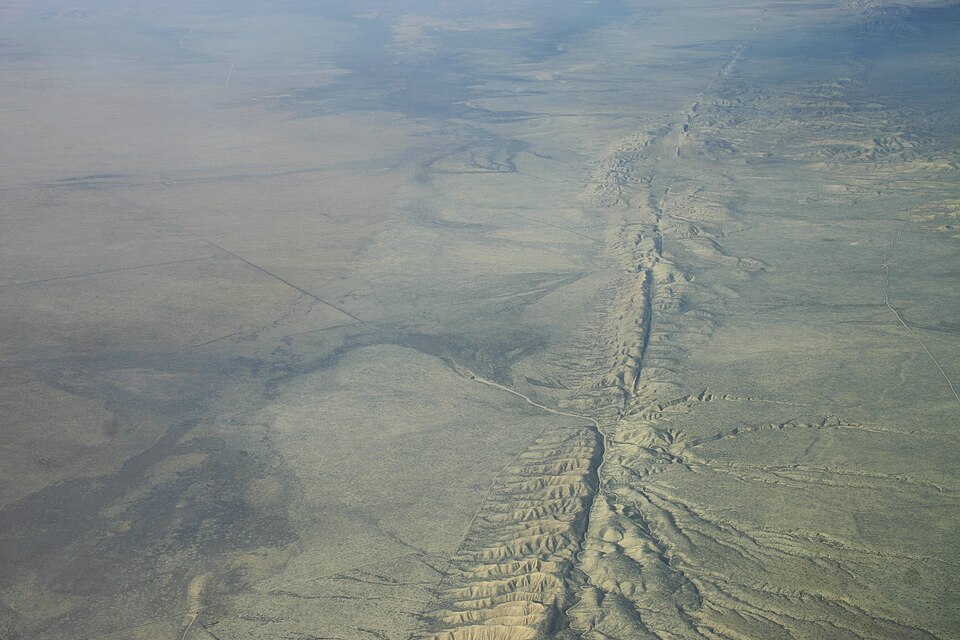
The San Andreas Fault in California is the best-studied strike-slip system in the world. It marks the boundary between the Pacific Plate to the west, which is moving northwestward, and the North American Plate to the east, which is moving southeastward in the relative frame, and the resulting offset is right-lateral. Geodetic measurements give a long-term slip rate of about 34 millimetres per year through central California, decreasing to roughly 20 millimetres per year north of the junction with the Calaveras and Concord faults and similarly tapering in the southern segments where slip is partitioned across the parallel San Jacinto and other strands. The total cumulative offset since the fault became active in its present form some 25 to 30 million years ago is several hundred kilometres.8, 9
The 1906 San Francisco earthquake was the event that converted the San Andreas from a known fault into the prototype of strike-slip behaviour. The shock ruptured nearly 480 kilometres of the surface trace from San Juan Bautista in the south to Shelter Cove in the north, with maximum surface displacements close to 6 metres near Olema in Marin County. The rupture moved horizontally rather than vertically, an observation that surprised contemporary geologists who had expected the same kind of vertical scarp formation that accompanies normal-fault earthquakes. Andrew Lawson chaired the State Earthquake Investigation Commission whose 1908 report compiled the field data, and the geophysicist Henry Fielding Reid analysed the survey lines crossing the fault to formulate the theory of elastic rebound. Reid showed that the ground on either side of the fault had been bending steadily for fifty years before the earthquake, accumulating about 3.2 metres of strain, and that the earthquake was the abrupt release of that stored elastic energy. Elastic rebound remains the foundation of all modern earthquake mechanics, and its experimental verification on the San Andreas was the first.8, 9
The historical earthquake record on the San Andreas is short, but the prehistoric record is long. At the Pallett Creek site in southern California, Kerry Sieh in the late 1970s used backhoe trenches across an old marsh to expose a continuous sediment record offset by past surface ruptures. By radiocarbon-dating the buried peat and silt layers, he established that more than twenty large earthquakes had occurred at the site over the past two millennia. A subsequent reanalysis using accelerator mass spectrometry radiocarbon dates by Scharer and colleagues refined the chronology and gave an average recurrence interval for large 1857-style earthquakes on this segment of about 100 to 135 years — with wide variability. The field of paleoseismology grew directly out of these excavations and is now applied to faults on every continent.16
Oblique-slip faults and partitioned deformation
Pure normal, reverse, and strike-slip end members are mathematical idealisations. Most natural faults host slip with components in more than one direction, and their classification as oblique faults is a matter of degree. By convention, an oblique fault is named for the dominant component — an “oblique right-lateral fault” has more horizontal than vertical slip with a right-lateral horizontal sense, while a “normal-oblique” fault has more dip-slip than strike-slip and a normal sense in the vertical direction. The rake angle quantifies the mixture: rakes of 45, 90, and 135 degrees on a fault dipping to the south correspond to right-oblique normal, pure normal, and left-oblique normal slip respectively.6, 18
The Denali Fault in Alaska illustrates how slip on a single curved fault can change character from one end to the other. The 2002 magnitude 7.9 Denali earthquake ruptured 341 kilometres of the fault, but the surface trace did not maintain a constant strike: its azimuth varied by more than 50 degrees over the rupture length. As a result, slip during the same earthquake was thrust-dominated on the western Susitna Glacier segment, transitioned to oblique-thrust on the central section, and became almost pure right-lateral strike-slip on the eastern Totschunda segment. The same regional strain field was thus expressed as three different fault types simultaneously, a striking demonstration of how local fault geometry rather than regional stress determines what kind of slip a particular patch of crust will experience.18
At regional scales, oblique convergence between two plates often produces strain partitioning, in which the dip-slip and strike-slip components are accommodated on separate parallel faults rather than on a single oblique structure. The Sumatra subduction zone is the canonical example: the obliquely converging Indo-Australian and Sunda plates are coupled across a nearly pure thrust megathrust offshore, while the strike-slip component of the relative motion is taken up onshore by the Great Sumatran Fault, a 1,900-kilometre dextral fault that runs the length of Sumatra parallel to the trench. Whether convergence is partitioned in this way or accommodated on a single oblique structure depends on the obliquity of the relative motion and on the relative strength of the plate interface and the overriding crust.18
Focal mechanisms and moment tensors
The Andersonian classification was originally derived from field mapping of exposed faults, but modern seismology recovers the same categories from radiation patterns of seismic waves. When an earthquake occurs, the slip on the fault generates a characteristic four-quadrant pattern of compressional and tensional first motions in the surrounding rock. By collecting first-motion polarities from seismograms recorded at stations distributed around the source, a seismologist can determine the orientation of the two possible nodal planes — one of which is the actual fault and the other an auxiliary plane perpendicular to the slip vector — and the direction of slip on each. The result is conventionally drawn as a “beach ball” diagram with shaded compressional quadrants, which encodes the strike, dip, and rake of the source.4, 21
The shape of a focal mechanism is diagnostic of fault type. A strike-slip earthquake produces a beach ball with two perpendicular vertical nodal planes and four sectors that meet at right angles in plan view. A normal-faulting earthquake produces a beach ball with the compressional quadrants on the outside, surrounding a central tensional zone — a pattern that looks like a bowtie viewed end-on. A thrust earthquake produces the opposite pattern, with a central compressional zone surrounded by tensional quadrants. Oblique events produce intermediate beach balls in which the nodal planes are tilted asymmetrically.4, 21
The full three-dimensional source description is the moment tensor, a symmetric 3 × 3 matrix whose six independent components describe the equivalent system of force couples acting at the source. Modern broadband stations and centroid moment tensor inversion projects, including the Global CMT catalogue at Columbia University, routinely recover moment tensors for every earthquake larger than about magnitude 5 anywhere on Earth. Statistical analysis of these catalogues confirms Anderson's three-fold classification: the overwhelming majority of earthquakes plot near one of the three idealised end members, and the rare events with strong non-double-couple components are typically associated with volcanic processes rather than ordinary faulting. Hardebeck and Hauksson used dense focal mechanism catalogues from southern California to invert for the local stress tensor, a technique that uses the same Anderson framework in reverse: from many fault-slip observations, infer the principal stress directions and the relative magnitudes of the three principal stresses.20, 21
Geomorphic expression of faults
Faults that reach the Earth's surface during earthquakes leave durable landforms whose morphology can be read to extract the fault's slip history. The most common is the fault scarp, a small cliff produced where one side of the rupture has been raised relative to the other. Normal faults produce free-face scarps where the footwall stands above the dropped hanging wall; reverse faults produce overhanging or vertical scarps along their leading edges; pure strike-slip faults produce no scarps at all but offset every linear feature they cross, from streams and ridges to fences and railroad tracks.22
Once formed, a scarp begins to degrade. Loose material at the top tumbles to the base, rainsplash and bioturbation move sediment downslope, and the originally sharp edge becomes progressively smoother. To a good approximation, the rate at which sediment moves downslope is proportional to the local gradient, so the diffusion equation describes the evolution of the profile. The diffusivity is a property of the substrate and the climate; once it has been calibrated against scarps of known age, the morphology of an undated scarp can be used to estimate when it formed. Carretier and colleagues applied morphological dating to cumulative reverse-fault scarps in the Gurvan Bogd system of Mongolia and recovered slip rates and earthquake recurrence intervals consistent with independent paleoseismic estimates. The technique fails for very old scarps, which lose all morphological memory of their initial shape, and for fault rocks where lithology rather than diffusion controls erosion, but for Holocene scarps in unconsolidated sediments it has become a standard tool.17, 22
The cumulative geomorphic expression of fault systems extends far beyond individual scarps. Range-bounding normal faults in the Basin and Range create the linear, faceted mountain fronts and triangular spur facets that are the diagnostic landscape of extensional terrain. Strike-slip faults produce linear valleys, beheaded streams, sag ponds, and shutter ridges where formerly continuous topography has been offset across the trace. Active thrust faults at the leading edge of fold-and-thrust belts produce growing anticlines whose flanks tilt progressively outward as slip accumulates, often visible in the deformed terraces of antecedent rivers. Each of these landform suites is a long-term record of repeated earthquakes, and tectonic geomorphology is the discipline that extracts that record.22
Fault dimensions and earthquake size
The size of an earthquake is set by the area of the fault that slips and the average displacement on it. The seismic moment M0 is the product of the rupture area, the average slip, and the elastic shear modulus of the surrounding rock, and the moment magnitude Mw is a logarithmic function of M0. Larger faults can host larger earthquakes because they have more area to rupture, so the maximum credible magnitude on a given fault is constrained by its geometry.4, 13
Donna Wells and Kevin Coppersmith compiled source parameters for hundreds of historical earthquakes worldwide in 1994 and derived empirical regressions linking moment magnitude to surface rupture length, subsurface rupture length, rupture area, and average and maximum displacement. The relationships hold for all three Andersonian fault types, with only modest differences in the regression coefficients between styles. As a rule of thumb, a fault that ruptures 10 kilometres of its surface trace produces an earthquake near magnitude 6.5; 100 kilometres produces near magnitude 7.5; 500 kilometres produces near magnitude 8.5; and the longest ruptures of about 1,300 kilometres on subduction megathrusts produce magnitudes near 9.1, the largest yet recorded on a clearly identified fault. The average ratio of surface rupture length to subsurface rupture length is about 0.75, with the surface ratio increasing toward unity for the largest events. These scaling relations are now standard inputs to probabilistic seismic hazard analyses worldwide.13
The maximum earthquake a fault can host also depends on its type, because the dimensions of the seismogenic crust set an upper limit on the downdip width of the rupture. Shallowly dipping thrust faults at subduction zones can have rupture widths of 100 to 200 kilometres, allowing them to host earthquakes that propagate over enormous areas. Steeply dipping strike-slip faults are limited to widths of 15 to 20 kilometres because the seismogenic zone is no deeper than that in continental crust, and the largest historical strike-slip earthquakes — such as the 1857 Fort Tejon and 1906 San Francisco events on the San Andreas, and the 1857 Bocono earthquake on the Bocono fault in Venezuela — rarely exceed magnitude 8. Normal faults are typically the smallest of the three end members, with the largest historical normal-faulting events near magnitude 7.5, because high differential stresses are difficult to maintain in extensional settings.4, 13
From Anderson to the modern classification
Anderson's original framework has survived three quarters of a century of refinement in remarkably intact form. The mechanical assumption that one principal stress is vertical near the surface remains an excellent first approximation, and the prediction that the three permutations of the principal axes correspond to the three observed fault types remains the foundation on which seismic hazard analyses are built. What has changed is the precision with which the framework can be applied. Modern methods combine focal mechanism inversions, geodetic strain rates from continuous GNSS networks, borehole stress measurements, and finite element simulations of the lithosphere to map the orientation and magnitude of the stress tensor across entire continents at kilometre resolution.20, 21
Newer questions concern the regimes Anderson did not address. The discovery of slow-slip events — transient aseismic ruptures lasting days to weeks that release seismic moments equivalent to large earthquakes without generating shaking — has revealed that the divide between brittle, seismic faulting and ductile, aseismic flow is not the sharp boundary the classical model assumed. Low-angle normal faults remain mechanically puzzling: they appear to slip, but they do so under stress conditions that violate Byerlee friction unless fluid pressures or fault-zone weakening are invoked. The mechanics of segmented faults, where slip arrests at geometric discontinuities such as bends and step-overs, link Anderson's idealised infinite plane to the real, finite, irregular structures imaged by modern lidar topography and high-resolution seismic reflection surveys.4, 11, 22
The classification of faults thus serves a double purpose. It is a kinematic scheme for describing what slip has occurred, and it is a mechanical scheme for predicting where slip will occur next. Both uses are encoded in the same three-fold division between extension, compression, and shear that Anderson published in 1951, and both depend on the same physical premise that brittle rock obeys a friction law that is roughly independent of rock type and inversely sensitive to fluid pressure. Every earthquake hazard map of California, Utah, Nepal, Japan, or Chile is built on this foundation.1, 2, 13
References
The Dynamics of Faulting and Dyke Formation with Applications to Britain (2nd edition)
The mechanics of the earthquake (Volume II of The California earthquake of April 18, 1906: Report of the State Earthquake Investigation Commission)
The California earthquake of April 18, 1906: Report of the State Earthquake Investigation Commission, Volume I
Low-angle normal faults in the Basin and Range Province: nappe tectonics in an extending orogen
The origin of metamorphic core complexes and detachment faults formed during Tertiary continental extension in the northern Colorado River region, U.S.A.
New empirical relationships among magnitude, rupture length, rupture width, rupture area, and surface displacement
Convergence rate across the Nepal Himalaya and interseismic coupling on the Main Himalayan Thrust: Implications for seismic hazard
A reevaluation of the Pallett Creek earthquake chronology based on new AMS radiocarbon dates, San Andreas fault, California
Morphological dating of cumulative reverse fault scarps: examples from the Gurvan Bogd fault system, Mongolia
Localized slip and distributed deformation in oblique settings: the example of the Denali fault system, Alaska
Earthquake focal mechanisms and the determination of stress orientations from seismic data